Introduction
The MFS-16 is a virtual computer, designed from scratch, with an original CPU instruction set and assembly language. The project attempts to be an accurate virtual representation of a theoretical computing system that could be implemented as real hardware.
The instruction set, assembly language, and general system architecture are entirely original, with particular inspiration taken from the Intel 8080 and Zilog Z80 instruction sets.
The MFS-16 code repository can be found here. The repository includes the core MFS-16 system, an assembler for assembling your own MFS-16 programs, and a desktop frontend with keyboard input, graphical display, user configuration, and a debugger.
Quick Start - Linux
1. Preparations
Ensure that you have rustup, git, CMake, and a C linker. A commonly-used C linker is included in the GCC toolchain.
2. Clone the Git repository
Clone the Git repo to a convenient place, then enter the new mfs16 directory.
git clone https://github.com/maxgmr/mfs16 && cd mfs16
3. Build the program
Generally speaking, the program needs to be built using the release profile in order to run at the proper clock speed.
cargo build --release
4. Run!
To run the hello world program:
target/release/mfs16desktop programs/hello_world
Why not try typing some text?
target/release/mfs16desktop programs/scribe
Configuration
By default, the user configuration file for MFS-16 desktop is found in one of the following locations:
- Linux:
~/.config/mfs16desktop/config.toml - macOS:
/Users/<USER>/Library/Caches/ca.maxgmr.mfs16desktop/config.toml - Windows:
C:\Users\<USER>\AppData\Local\maxgmr\mfs16desktop\config\config.toml
However, this path can be overridden by setting the MFS16DESKTOP_CONFIG environment variable.
config.toml can be edited by opening the file in any text editor. Any missing options will be overwritten by default.toml in the same directory.
Configuration Options
Palette Settings
-
preset_palette: The preset MFS-16 colour palette to be used.
This allows for easy switching between certain predefined colour schemes. The preset palettes are defined in the table below- simply replace the string in the config file with any one of the preset names in the table.
| Preset Name |
|---|
| default |
| gruvbox |
| gruvbox_light |
[palette_settings]
preset_palette = "Gruvbox" # case-insensitive
Path Settings
- data_path: The path to the data directory where the virtual hard drives are stored.
[path_settings]
data_path = "~/path/to/data/directory"
Key Bindings
- exit: The key which, when pressed, immediately exits the program. Must be a valid SDL2 Scancode.
[key_bindings]
exit = "Escape"
Debugger Settings
-
history_size: The number of cycles to record before the breakpoint is reached.
-
cycles_after_break: The number of cycles to record after the breakpoint is reached.
-
mem_ranges: The ranges of memory to record when keeping track of computer state.
[debugger_settings]
history_size = 128
cycles_after_break = 32

[[debugger_settings.mem_ranges]]
start = 0xFFFFCF
end = 0xFFFFFF

[[debugger_settings.mem_ranges]]
...
Note that all non-empty break criteria must be satisfied for the debugger to break.
-
break_criteria.pc_list: Break if the program counter is any one of the values in the list.
-
break_criteria.ei: Break if interrupts get enabled.
-
break_criteria.pc_upper_bound: Break if the program counter is greater than this value.
-
break_criteria.pc_lower_bound: Break if the program counter is lesser than this value.
-
break_criteria.instr_list: Break if the current instruction matches any instruction in the list.
-
break_criteria.reg_upper_bounds: Break if any register in this list is greater than its corresponding value.
-
break_criteria.reg_lower_bounds: Break if any register in this list is lesser than its corresponding value.
[debugger_settings.break_criteria]
pc_list = [0x144, 0xABC]
ei = true
pc_upper_bound = 0xFFFFFF
pc_lower_bound = 0x000000

[[debugger_settings.break_criteria.instr_list]]
CmpVraImm8 = "E0"

[[debugger_settings.break_criteria.instr_list]]
LdBraRb = ["DE", "C"]

[[debugger_settings.break_criteria.instr_list]]
BitRaB = ["A", 0]

# OR...
[debugger_settings.break_criteria]
instr_list = ["EI"]
...

[[debugger_settings.break_criteria.reg_upper_bounds]]
reg = "E"
val = 0xFFF0

[[debugger_settings.break_criteria.reg_upper_bounds]]
reg = "L"
val = 0x1234
...

[[debugger_settings.break_criteria.reg_lower_bounds]]
reg = "E"
val = 0x0200
...
CPU
The CPU runs at ~33.55 MHz (33 554 432 Hz), meaning it performs ~33 million cycles per second. It can read one 16-bit word per cycle.
Registers
The CPU has 7 general-purpose registers: A, B, C, D, E, H, and L. Each register can store a single 16-bit word at a time.
Adjacent registers can be combined and accessed as a 32-bit double word "big register": BC, DE, and HL. These are most commonly used for indexing the 32-bit memory bus.
The high (x1) and low (x0) bytes of each register can be virtually accessed individually: A1, A0, B1, B0, C1, C0, D1, D0, E1, E0, H1, H0, L1, and L0.
The vast majority of CPU instructions are register-agnostic. Therefore, any register can be used as operands and/or outputs for all instructions.
Flags
The CPU has 5 flags that can be set and/or reset by some CPU instructions. The 5 flags are as follows:
("iff" is short for "if and only if".)
-
Z (Zero): This flag is typically set iff the result of the CPU instruction is equal to 0.
-
C (Carry): This flag is typically set iff the result of the CPU instruction exceeds the available bits reserved for the output.
-
O (Overflow): This flag is typically set iff the result of the CPU instruction is too large or too small to fit in the available bits when interpreted as a signed value. In contrast to the Carry flag, which usually only necessitates using the Carry flag in future operations, the Overflow flag usually means an error has occurred, assuming the goal of the instruction was to perform signed operations.
-
P (Parity): This flag is typically set iff the result of the CPU instruction is even. Internally, the flag is set iff the lowest bit of the result is 0.
-
N (Negative): This flag is typically set iff the result of the CPU instruction is negative when interpreted as a signed value. Internally, the flag is set iff the highest bit of the result is 1.
Interrupts
Interrupts can be handled by the CPU in order to deal with events in a timely manner.
Interrupt Types
The interrupt types are listed from highest to lowest priority.
-
Frame: This interrupt is triggered periodically at each frame. This will always happen after a set number of cycles.
-
Keyboard: When any bit in the keyboard register changes from 0 to 1, the Keyboard interrupt is triggered.
-
Error: When any bit in the error register changes from 0 to 1, (i.e., an error occurs), the Error interrupt is triggered.
Interrupt Handling Logic
The CPU performs the following actions every cycle:
-
First, the CPU checks to see if it is halted or the master interrupt flag is set. If the CPU is not halted AND the master interrupt flag is reset, then it does nothing.
-
After that, the CPU uses the interrupt enable register as a bitmask for the interrupt register to check to see if any enabled interrupts have been triggered.
-
If no enabled interrupts have been triggered, then nothing happens and the CPU leaves its interrupt handling logic.
-
Otherwise, if the CPU is in a halted state, regardless of the state of the master interrupt flag, then the CPU will be taken out of its halted state.
-
The CPU then looks at the lowest bit of the interrupts register that has been activated or enabled. In other words, the CPU prioritises lower-bit interrupts first.
-
Finally, the CPU disables the master interrupt flag and jumps to the static ROM address of its respective interrupt handler. The address is
0x100 + (0x100 * interrupt bit number). For example, theFrameinterrupt is bit 0 of the interrupt enable and interrupt registers. This means that the CPU jumps to address0x100when aFrameinterrupt is triggered. TheKeyboardinterrupt is bit 1, so the CPU jumps to address0x200when aKeyboardinterrupt is triggered.
Master Interrupt Flag
This internal CPU flag (i.e., inaccessible by memory bus) can globally enable or disable any interrupt handling whatsoever. If this flag is reset, then any triggered interrupts can only take the CPU out of the halted state. It cannot be read directly, and is only modified in the following ways:
- Reset:
DIinstruction, execution of interrupt handler - Set:
EIinstrution,RETIinstruction
The master interrupt flag is reset when the computer boots.
Interrupt Enable Register
Each bit of this 1-byte register corresponds to a different type of interrupt. A set bit means that the corresponding interrupt is enabled and can therefore be handled by the CPU, and vice versa.
The interrupt at bit 0 is handled with the highest priority, and the interrupt at bit 7 is handled with the lowest priority.
This register must be set explicitly by writing to address 0xFFFF_FFFE.
| 7 6 5 4 3 | 2 | 1 | 0 |
|---|---|---|---|
| Error | Keyboard | Frame |
Interrupt Register
The bits of this 1-byte register correspond to the same interrupts as the interrupt enable register. A set bit means that the corresponding interrupt has been triggered, but the interrupt will only be handled if the same bit in the interrupt enable register and the master interrupt flag are both set.
The interrupt at bit 0 is handled with the highest priority, and the interrupt at bit 7 is handled with the lowest priority.
Bits in this register is usually set naturally when their respective events occur, but interrupts can be "force-triggered" by manually writing to the register at 0xFFFF_FFFF.
| 7 6 5 4 3 2 | 1 | 0 |
|---|---|---|
| Keyboard | Frame |
Instruction Set
This is the list of MFS-16 CPU instructions. Each opcode is 16 bits + the length of the immediate value (if any).
Instructions do not affect CPU flags unless otherwise specified. Any flags omitted by an instruction's list of affected flags are unaffected by the instruction.
Conditional instructions can take different amounts of cycles, depending on whether or not the condition is satisfied.
"iff" is short for "if and only if".
Legend
-
rn: 16-bit register n. (A, B, C, D, E, H, L).
-
brn: 32-bit big register n. (BC, DE, HL).
-
vrn: 8-bit virtual register n. (A1, A0, B1, B0, C1, C0, D1, D0, E1, E0, H1, H0, L1, L0).
-
imm16: The 16-bit immediate value after this instruction.
-
imm32: The 32-bit immediate value after this instruction.
-
imm8: The 8-bit immediate value after this instruction.
-
u4: 4-bit unsigned integer constant (0x0 to 0xF).
-
SP: The stack pointer.
-
Z: The Zero flag.
-
C: The Carry flag.
-
O: The Overflow flag.
-
P: The Parity flag.
-
N: The Negative flag.
Consider this example on reading the notation. instruction LD ra, rb with opcode 0x01ab means that any combination of 16-bit registers can be entered. LD A, B has opcode 0x0101, while LD L, C has opcode 0x0162.
Instructions
-
NOP: Do nothing.
Opcode: 0x0000
Cycles: 2 -
LD ra, rb: Load rb into ra.
Opcode: 0x01ab
Cycles: 2 -
LD bra, brb: Load brb into bra.
Opcode: 0x01(a+7)(b+7)
Cycles: 2 -
LD SP,imm32: Load imm32 into SP.
Opcode: 0x01A0
Cycles: 4 -
LD [imm32], SP: Load SP into address imm32.
Opcode: 0x01A1
Cycles: 4 -
LD SP, bra: Load bra into SP.
Opcode: 0x01Ba
Cycles: 2 -
LD bra, SP: Load SP into bra.
Opcode: 0x01Ca
Cycles: 2 -
LD vra, vrb: Load vrb into vra.
Opcode: 0x02ab
Cycles: 2 -
LD ra, imm16: Load imm16 into ra.
Opcode: 0x030a
Cycles: 3 -
LD bra, imm32: Load imm32 into bra.
Opcode: 0x031a
Cycles: 4 -
LD vra, imm8: Load imm8 into vra.
Opcode: 0x032a
Cycles: 3 -
LD [bra], imm16: Load imm16 into address bra.
Opcode: 0x033a
Cycles: 3 -
LD [bra], rb: Load rb into address bra.
Opcode: 0x04ab
Cycles: 3 -
LD ra, [brb]: Load the value at address brb into ra.
Opcode: 0x05ab
Cycles: 3 -
LDR ra, imm32: Load the value at (HL + imm32 interpreted as a signed integer) into ra.
Opcode: 0x057a
Cycles: 5 -
LDI [bra], rb: Load rb into address bra, then increase bra by two.
Opcode: 0x06ab
Cycles: 3 -
LDD [bra], rb: Load rb into address bra, then decrease bra by two.
Opcode: 0x07ab
Cycles: 3 -
LDI ra, [brb]: Load the value at brb into address ra, then increase brb by two.
Opcode: 0x08ab
Cycles: 3 -
LDD ra, [brb]: Load the value at brb into address ra, then decrease brb by two.
Opcode: 0x09ab
Cycles: 3 -
LDI [bra], imm16: Load imm16 into address bra, then increment bra by two.
Opcode: 0x097a
Cycles: 3 -
LDD [bra], imm16: Load imm16 into address bra, then decrement bra by two.
Opcode: 0x098a
Cycles: 3 -
LD [imm32], ra: Load ra into address imm32.
Opcode: 0x099a
Cycles: 4 -
LD ra, [imm32]: Load the value at imm32 into ra.
Opcode: 0x09Aa
Cycles: 4 -
VLD [bra], brb: VRAM load. Faster 32-bit version of LD [bra], rb for VRAM addresses only.
Opcode: 0x0Aab
Cycles: 2 -
VLDI [bra], brb: VRAM load. Faster 32-bit version of LDI [bra], rb for VRAM addresses only.
Opcode: 0x0Bab
Cycles: 2 -
VLDD [bra], brb: VRAM load. Faster 32-bit version of LDD [bra], rb for VRAM addresses only.
Opcode: 0x0Cab
Cycles: 2 -
VLD [bra], imm32: VRAM load. Faster 32-bit version of VLD [bra], imm32 for VRAM addresses only.
Opcode: 0x0C3a
Cycles: 4 -
VLDI [bra], imm32: VRAM load. Faster 32-bit version of VLDI [bra], imm32 for VRAM addresses only.
Opcode: 0x0C4a
Cycles: 4 -
VLDD [bra], imm32: VRAM load. Faster 32-bit version of VLDI [bra], imm32 for VRAM addresses only.
Opcode: 0x0C5a
Cycles: 4 -
ADD ra, rb: ra += rb.
Opcode: 0x10ab
Cycles: 2
Flags:- Set Z iff the result == 0.
- Set C iff the result exceeds the available bits.
- Set O iff the signed result is too large or small to fit in the available bits.
- Set P iff the result is even.
- Set N iff the result is negative when interpreted as a signed value.
-
ADD bra, brb: bra += brb.
Opcode: 0x10(a+7)(b+7)
Cycles: 2
Flags: See ADD ra, rb. -
ADD vra, vrb: vra += vrb.
Opcode: 0x11ab
Cycles: 2
Flags: See ADD ra, rb. -
ADC ra, rb: ra += rb + C.
Opcode: 0x12ab
Cycles: 2
Flags: See ADD ra, rb. -
ADC bra, brb: bra += brb + C.
Opcode: 0x12(a+7)(b+7)
Cycles: 2
Flags: See ADD ra, rb. -
ADC vra, vrb: vra += vrb + C.
Opcode: 0x13ab
Cycles: 2
Flags: See ADD ra, rb. -
SUB ra, rb: ra -= rb.
Opcode: 0x14ab
Cycles: 2
Flags:- Set Z iff the result == 0.
- Set C iff rb > ra for SUB instructions. Set C iff (rb + C) > ra for SBB instructions.
- Set O iff the signed result is too large or too small to fit in the available bits.
- Set P iff the result is even.
- Set N iff the result is negative when interpreted as a signed value.
-
SUB bra, brb: bra -= brb.
Opcode: 0x14(a+7)(b+7)
Cycles: 2
Flags: See SUB ra, rb. -
SUB vra, vrb: vra -= vrb.
Opcode: 0x15ab
Cycles: 2
Flags: See SUB ra, rb. -
SBB ra, rb: ra -= rb + C.
Opcode: 0x16ab
Cycles: 2
Flags: See SUB ra, rb. -
SBB bra, brb: bra -= brb + C.
Opcode: 0x16(a+7)(b+7)
Cycles: 2
Flags: See SUB ra, rb. -
SBB vra, vrb: vra -= vrb + C.
Opcode: 0x17ab
Cycles: 2
Flags: See SUB ra, rb. -
ADD ra, imm16: ra += imm16.
Opcode: 0x180a
Cycles: 3
Flags: See ADD ra, rb. -
ADC ra, imm16: ra += imm16 + C.
Opcode: 0x181a
Cycles: 3
Flags: See ADD ra, rb. -
ADD bra, imm32: bra += imm32.
Opcode: 0x182a
Cycles: 4
Flags: See ADD ra, rb. -
ADC bra, imm32: bra += imm32 + C.
Opcode: 0x183a
Cycles: 4
Flags: See ADD ra, rb. -
ADD vra, imm8: vra += imm8.
Opcode: 0x184a
Cycles: 3
Flags: See ADD ra, rb. -
ADC vra, imm8: vra += imm8 + C.
Opcode: 0x185a
Cycles: 3
Flags: See ADD ra, rb. -
SUB ra, imm16: ra -= imm16.
Opcode: 0x186a
Cycles: 3
Flags: See SUB ra, rb. -
SBB ra, imm16: ra -= imm16 + C.
Opcode: 0x187a
Cycles: 3
Flags: See SUB ra, rb. -
SUB bra, imm32: bra -= imm32.
Opcode: 0x188a
Cycles: 4
Flags: See SUB ra, rb. -
SBB bra, imm32: bra -= imm32 + C.
Opcode: 0x189a
Cycles: 4
Flags: See SUB ra, rb. -
SUB vra, imm8: vra -= imm8.
Opcode: 0x18Aa
Cycles: 3
Flags: See SUB ra, rb. -
SBB vra, imm8: vra -= imm8 + C.
Opcode: 0x18Ba
Cycles: 3
Flags: See SUB ra, rb. -
ADD ra, [brb]: ra += (the value at brb).
Opcode: 0x19ab
Cycles: 3
Flags: See ADD ra, rb. -
ADC ra, [brb]: ra += (the value at brb) + C.
Opcode: 0x1Aab
Cycles: 3
Flags: See ADD ra, rb. -
SUB ra, [brb]: ra -= (the value at brb).
Opcode: 0x1Bab
Cycles: 3
Flags: See SUB ra, rb. -
SBB ra, [brb]: ra -= (the value at brb) + C.
Opcode: 0x1Cab
Cycles: 3
Flags: See SUB ra, rb. -
TCP ra: Two's complement ra. ra = -ra.
Opcode: 0x1D0a
Cycles: 2
Flags:- Set Z iff the result == 0.
- Set C iff the result != 0.
- Set O iff the signed result is too large or too small to fit in the available bits.
- Set P iff the result is even.
- Set N iff the result is negative when interpreted as a signed value.
-
TCP bra: Two's complement bra. bra = -bra.
Opcode: 0x1D1a
Cycles: 2
Flags: See TCP ra. -
TCP vra: Two's complement vra. vra = -vra.
Opcode: 0x1D2a
Cycles: 2
Flags: See TCP ra. -
INC ra: Increment ra. ra += 1.
Opcode: 0x1D3a
Cycles: 2
Flags:- Set Z iff the result == 0.
- Set P iff the result is even.
-
INC bra: Increment bra. bra += 1.
Opcode: 0x1D4a
Cycles: 2
Flags: See INC ra. -
INC vra: Increment vra. vra += 1.
Opcode: 0x1D5a
Cycles: 2
Flags: See INC ra. -
DEC ra: Decrement ra. ra -= 1.
Opcode: 0x1D6a
Cycles: 2
Flags: See INC ra. -
DEC bra: Decrement bra. bra -= 1.
Opcode: 0x1D7a
Cycles: 2
Flags: See INC ra. -
DEC vra: Decrement vra. vra -= 1.
Opcode: 0x1D8a
Cycles: 2
Flags: See INC ra. -
PSS ra: Set the CPU flags based on the value of ra.
Opcode: 0x1D9a
Cycles: 2
Flags:- Set Z iff the value == 0.
- Set P iff the value is even.
- Set N iff the value is negative when interpreted as a signed integer.
-
PSS bra: Set the CPU flags based on the value of bra.
Opcode: 0x1DAa
Cycles: 2
Flags: See PSS ra. -
PSS vra: Set the CPU flags based on the value of vra.
Opcode: 0x1DBa
Cycles: 2
Flags: See PSS ra. -
PSS imm16: Set the CPU flags based on the value of imm16.
Opcode: 0x1DC0
Cycles: 3
Flags: See PSS ra. -
PSS imm32: Set the CPU flags based on the value of imm32.
Opcode: 0x1DC1
Cycles: 4
Flags: See PSS ra. -
PSS imm8: Set the CPU flags based on the value of imm8.
Opcode: 0x1DC2
Cycles: 3
Flags: See PSS ra. -
AND ra, rb: Bitwise AND. ra &= rb.
Opcode: 0x1Eab
Cycles: 2
Flags:- Set Z iff the result == 0.
- Reset C.
- Reset O.
- Set P iff the result is even.
- Set N iff the result is negative when interpreted as a signed integer.
-
AND bra, brb: Bitwise AND. bra &= brb.
Opcode: 0x1Fab
Cycles: 2
Flags: See AND ra, rb. -
AND vra, vrb: Bitwise AND. vra &= vrb.
Opcode: 0x20ab
Cycles: 2
Flags: See AND ra, rb. -
AND ra, [brb]: Bitwise AND. ra &= (the value at brb).
Opcode: 0x21ab
Cycles: 3
Flags: See AND ra, rb. -
OR ra, rb: Bitwise OR. ra |= rb.
Opcode: 0x22ab
Cycles: 2
Flags: See AND ra, rb. -
OR bra, brb: Bitwise OR. bra |= brb.
Opcode: 0x23ab
Cycles: 2
Flags: See AND ra, rb. -
OR vra, vrb: Bitwise OR. vra |= vrb.
Opcode: 0x24ab
Cycles: 2
Flags: See AND ra, rb. -
OR ra, [brb]: Bitwise OR. ra |= (the value at brb).
Opcode: 0x25ab
Cycles: 3
Flags: See AND ra, rb. -
XOR ra, rb: Bitwise XOR. ra ^= rb.
Opcode: 0x26ab
Cycles: 2
Flags: See AND ra, rb. -
XOR bra, brb: Bitwise XOR. bra ^= brb.
Opcode: 0x27ab
Cycles: 2
Flags: See AND ra, rb. -
XOR vra, vrb: Bitwise XOR. vra ^= vrb.
Opcode: 0x28ab
Cycles: 2
Flags: See AND ra, rb. -
XOR ra, [brb]: Bitwise XOR. ra ^= (the value at brb).
Opcode: 0x29ab
Cycles: 3
Flags: See AND ra, rb. -
AND ra, imm16: Bitwise AND. ra &= imm16.
Opcode: 0x2A0a
Cycles: 3
Flags: See AND ra, rb. -
AND bra, imm32: Bitwise AND. bra &= imm32.
Opcode: 0x2A1a
Cycles: 4
Flags: See AND ra, rb. -
AND vra, imm8: Bitwise AND. vra &= imm8.
Opcode: 0x2A2a
Cycles: 3
Flags: See AND ra, rb. -
OR ra, imm16: Bitwise OR. ra |= imm16.
Opcode: 0x2A3a
Cycles: 3
Flags: See AND ra, rb. -
OR bra, imm32: Bitwise OR. bra |= imm32.
Opcode: 0x2A4a
Cycles: 4
Flags: See AND ra, rb. -
OR vra, imm8: Bitwise OR. vra |= imm8.
Opcode: 0x2A5a
Cycles: 3
Flags: See AND ra, rb. -
XOR ra, imm16: Bitwise XOR. ra ^= imm16.
Opcode: 0x2A6a
Cycles: 3
Flags: See AND ra, rb. -
XOR bra, imm32: Bitwise XOR. bra ^= imm32.
Opcode: 0x2A7a
Cycles: 4
Flags: See AND ra, rb. -
XOR vra, imm8: Bitwise XOR. vra ^= imm8.
Opcode: 0x2A8a
Cycles: 3
Flags: See AND ra, rb. -
NOT ra: Flip all bits of ra. ra = !ra.
Opcode: 0x2A9a
Cycles: 2
Flags: See AND ra, rb. -
NOT bra: Flip all bits of bra. bra = !bra.
Opcode: 0x2AAa
Cycles: 2
Flags: See AND ra, rb. -
NOT vra: Flip all bits of vra. vra = !vra.
Opcode: 0x2ABa
Cycles: 2
Flags: See AND ra, rb. -
ASR ra, u4: Arithmetic shift. Shift ra right u4 bits, preserving the most significant bit.
Opcode: 0x2Bab
Cycles: 2
Flags:- Set C iff the last bit shifted out == 1.
- Reset O.
-
ASR bra, u4: Arithmetic shift. Shift bra right u4 bits, preserving the most significant bit.
Opcode: 0x2Cab
Cycles: 2
Flags: See ASR ra, u4. -
ASR vra, u4: Arithmetic shift. Shift vra right u4 bits, preserving the most significant bit.
Opcode: 0x2Dab
Cycles: 2
Flags: See ASR ra, u4. -
ASL ra, u4: Arithmetic shift. Shift ra left u4 bits, shifting on zeroes.
Opcode: 0x2Eab
Cycles: 2
Flags:- Set C iff the last bit shifted out == 1.
- Set O iff the result's most significant bit is different than the original operand's most significant bit.
-
ASL bra, u4: Arithmetic shift. Shift bra left u4 bits, shifting on zeroes.
Opcode: 0x2Fab
Cycles: 2
Flags: See ASL ra, u4. -
ASL vra, u4: Arithmetic shift. Shift vra left u4 bits, shifting on zeroes.
Opcode: 0x30ab
Cycles: 2
Flags: See ASL ra, u4. -
LSR ra, u4: Logical shift. Shift ra right u4 bits, shifting on zeroes.
Opcode: 0x31ab
Cycles: 2
Flags:- Set C iff the last bit shifted out == 1.
- Set O iff the most significant bit of the original operand == 1.
-
LSR bra, u4: Logical shift. Shift bra right u4 bits, shifting on zeroes.
Opcode: 0x32ab
Cycles: 2
Flags: See LSR ra, u4. -
LSR vra, u4: Logical shift. Shift vra right u4 bits, shifting on zeroes.
Opcode: 0x33ab
Cycles: 2
Flags: See LSR ra, u4. -
RTR ra, u4: Rotate ra right u4 bits.
Opcode: 0x34ab
Cycles: 2
Flags:- Set C iff the last bit carried over to the other side == 1.
- Set O iff the result's most significant bit is different than the original operand's most significant bit.
-
RTR bra, u4: Rotate bra right u4 bits.
Opcode: 0x35ab
Cycles: 2
Flags: See RTR ra, u4. -
RTR vra, u4: Rotate vra right u4 bits.
Opcode: 0x36ab
Cycles: 2
Flags: See RTR ra, u4. -
RTL ra, u4: Rotate ra left u4 bits.
Opcode: 0x37ab
Cycles: 2
Flags: See RTR ra, u4. -
RTL bra, u4: Rotate bra left u4 bits.
Opcode: 0x38ab
Cycles: 2
Flags: See RTR ra, u4. -
RTL vra, u4: Rotate vra left u4 bits.
Opcode: 0x39ab
Cycles: 2
Flags: See RTR ra, u4. -
RCR ra, u4: Rotate ra right u4 bits through the carry flag.
Opcode: 0x3Aab
Cycles: 2
Flags:- C will be set iff the bit rotated into C == 1.
- Set O iff the result's most significant bit is different than the original operand's most significant bit.
-
RCR bra, u4: Rotate bra right u4 bits through the carry flag.
Opcode: 0x3Bab
Cycles: 2
Flags: See RCR ra, u4. -
RCR vra, u4: Rotate vra right u4 bits through the carry flag.
Opcode: 0x3Cab
Cycles: 2
Flags: See RCR ra, u4. -
RCL ra, u4: Rotate ra left u4 bits through the carry flag.
Opcode: 0x3Dab
Cycles: 2
Flags: See RCR ra, u4. -
RCL bra, u4: Rotate bra left u4 bits through the carry flag.
Opcode: 0x3Eab
Cycles: 2
Flags: See RCR ra, u4. -
RCL vra, u4: Rotate vra left u4 bits through the carry flag.
Opcode: 0x3Fab
Cycles: 2
Flags: See RCR ra, u4. -
CMP ra, rb: Set the flags according to the result of ra - rb, discarding the result.
Opcode: 0x40ab
Cycles: 2
Flags: See SUB ra, rb. -
CMP bra, brb: Set the flags according to the result of bra - brb, discarding the result.
Opcode: 0x40(a+7)(b+7)
Cycles: 2
Flags: See SUB ra, rb. -
CMP vra, vrb: Set the flags according to the result of vra - vrb, discarding the result.
Opcode: 0x41ab
Cycles: 2
Flags: See SUB ra, rb. -
CMP ra, imm16: Set the flags according to the result of ra - imm16, discarding the result.
Opcode: 0x420a
Cycles: 3
Flags: See SUB ra, rb. -
CMP bra, imm32: Set the flags according to the result of bra - imm32, discarding the result.
Opcode: 0x421a
Cycles: 4
Flags: See SUB ra, rb. -
CMP vra, imm8: Set the flags according to the result of vra - imm8, discarding the result.
Opcode: 0x422a
Cycles: 3
Flags: See SUB ra, rb. -
CMP imm16, ra: Set the flags according to the result of imm16 - ra, discarding the result.
Opcode: 0x423a
Cycles: 3
Flags: See SUB ra, rb. -
CMP imm32, bra: Set the flags according to the result of imm32 - bra, discarding the result.
Opcode: 0x424a
Cycles: 4
Flags: See SUB ra, rb. -
CMP imm8, vra: Set the flags according to the result of imm8 - vra, discarding the result.
Opcode: 0x425a
Cycles: 3
Flags: See SUB ra, rb. -
CMP ra, [brb]: Set the flags according to the result of ra - (the value at brb), discarding the result.
Opcode: 0x43ab
Cycles: 3
Flags: See SUB ra, rb. -
CMP [bra], rb: Set the flags according to the result of (the value at bra) - rb, discarding the result.
Opcode: 0x44ab
Cycles: 5
Flags: See SUB ra, rb. -
BIT ra, u4: Set the Zero flag according to bit u4 of ra.
Opcode: 0x45ab
Cycles: 2
Flags:- Set Z iff bit u4 of the given value == 0.
-
BIT [bra], u4: Set the Zero flag according to bit u4 of the value at bra.
Opcode: 0x46ab
Cycles: 3
Flags: See BIT ra, u4. -
STB ra, u4: Set bit u4 of ra.
Opcode: 0x47ab
Cycles: 2 -
STB [bra], u4: Set bit u4 of the value at bra.
Opcode: 0x48ab
Cycles: 3 -
RSB ra, u4: Reset bit u4 of ra.
Opcode: 0x49ab
Cycles: 2 -
RSB [bra], u4: Reset bit u4 of the value at bra.
Opcode: 0x4Aab
Cycles: 3 -
TGB ra, u4: Toggle bit u4 of ra.
Opcode: 0x4Bab
Cycles: 2 -
TGB [bra], u4: Toggle bit u4 of the value at bra.
Opcode: 0x4Cab
Cycles: 3 -
SWP ra: Swap the high and low bytes of ra.
Opcode: 0x4D0a
Cycles: 2 -
SWP [bra]: Swap the high and low bytes of the value at bra.
Opcode: 0x4D1a
Cycles: 3 -
SZF: Set the Zero flag.
Opcode: 0x4D20
Cycles: 2
Flags:- Set Z.
-
RZF: Reset the Zero flag.
Opcode: 0x4D21
Cycles: 2
Flags:- Reset Z.
-
TZF: Toggle the Zero flag.
Opcode: 0x4D22
Cycles: 2
Flags:- Set Z iff Z is currently reset.
-
SCF: Set the Carry flag.
Opcode: 0x4D23
Cycles: 2
Flags:- Set C.
-
RCF: Reset the Carry flag.
Opcode: 0x4D24
Cycles: 2
Flags:- Reset C.
-
TCF: Toggle the Carry flag.
Opcode: 0x4D25
Cycles: 2
Flags:- Set C iff C is currently reset.
-
SOF: Set the Overflow flag.
Opcode: 0x4D26
Cycles: 2
Flags:- Set O.
-
ROF: Reset the Overflow flag.
Opcode: 0x4D27
Cycles: 2
Flags:- Reset O.
-
TOF: Toggle the Overflow flag.
Opcode: 0x4D28
Cycles: 2
Flags:- Set O iff O is currently reset.
-
SPF: Set the Parity flag.
Opcode: 0x4D29
Cycles: 2
Flags:- Set P.
-
RPF: Reset the Parity flag.
Opcode: 0x4D2A
Cycles: 2
Flags:- Reset P.
-
TPF: Toggle the Parity flag.
Opcode: 0x4D2B
Cycles: 2
Flags:- Set P iff P is currently reset.
-
SNF: Set the Negative flag.
Opcode: 0x4D2C
Cycles: 2
Flags:- Set N.
-
RNF: Reset the Negative flag.
Opcode: 0x4D2D
Cycles: 2
Flags:- Reset N.
-
TNF: Toggle the Negative flag.
Opcode: 0x4D2E
Cycles: 2
Flags:- Set N iff N is currently reset.
-
SAF: Set all flags.
Opcode: 0x4D2F
Cycles: 2
Flags:- Set Z.
- Set C.
- Set O.
- Set P.
- Set N.
-
RAF: Reset all flags.
Opcode: 0x4D30
Cycles: 2
Flags:- Reset Z.
- Reset C.
- Reset O.
- Reset P.
- Reset N.
-
MULU ra, rb: Unsigned multiplication. ra *= rb.
Opcode: 0x50ab
Cycles: 2
Flags:- Set Z iff the result == 0.
- Set C iff the result exceeds the available bits.
- Set P iff the result is even.
- Set N iff the result is negative when interpreted as a signed integer.
-
MULI ra, rb: Signed multiplication. ra *= rb.
Opcode: 0x51ab
Cycles: 2
Flags:- Set Z iff the result == 0.
- Set O iff the result is too large or small to fit in the available bits.
- Set P iff the result is even.
- Set N iff the result is negative when interpreted as a signed integer.
-
DIVU ra, rb: Unsigned division. Does nothing if rb == 0. Stores the remainder in rb. ra /= rb.
Opcode: 0x52ab
Cycles: 2
Flags:- Set Z iff the result == 0.
- Set P iff the result is even.
- Set N iff the result is negative when interpreted as a signed integer.
-
DIVI ra, rb: Signed division. Does nothing if rb == 0. Stores the remainder in rb. ra /= rb.
Opcode: 0x53ab
Cycles: 2
Flags:- Set Z iff the result == 0.
- Set O iff the numerator is the biggest negative number of its data type and the denominator is -1.
- Set P iff the result is even.
- Set N iff the result is negative when interpreted as a signed integer.
-
MULU bra, brb: Unsigned multiplication. bra *= brb.
Opcode: 0x50(a+7)(b+7)
Cycles: 2
Flags: See MULU ra, rb. -
MULI bra, brb: Signed multiplication. bra *= brb.
Opcode: 0x51(a+7)(b+7)
Cycles: 2
Flags: See MULI ra, rb. -
DIVU bra, brb: Unsigned division. Stores the remainder in brb. bra /= brb.
Opcode: 0x52(a+7)(b+7)
Cycles: 2
Flags: See DIVU ra, rb. -
DIVI bra, brb: Signed division. Stores the remainder in brb. bra /= brb.
Opcode: 0x53(a+7)(b+7)
Cycles: 2
Flags: See DIVI ra, rb. -
MULU vra, vrb: Unsigned multiplication. vra *= vrb.
Opcode: 0x54ab
Cycles: 2
Flags: See MULU ra, rb. -
MULI vra, vrb: Signed multiplication. vra *= vrb.
Opcode: 0x55ab
Cycles: 2
Flags: See MULI ra, rb. -
DIVU vra, vrb: Unsigned division. Stores the remainder in vrb. vra /= vrb.
Opcode: 0x56ab
Cycles: 2
Flags: See DIVU ra, rb. -
DIVI vra, vrb: Signed division. Stores the remainder in vrb. vra /= vrb.
Opcode: 0x57ab
Cycles: 2
Flags: See DIVI ra, rb. -
MULU ra, [brb]: Unsigned multiplication. ra *= (the value at brb).
Opcode: 0x58ab
Cycles: 3
Flags: See MULU ra, rb. -
MULI ra, [brb]: Signed multiplication. ra *= (the value at brb).
Opcode: 0x59ab
Cycles: 3
Flags: See MULI ra, rb. -
DIVU ra, [brb]: Unsigned division. Stores the remainder in brb. ra *= (the value at brb).
Opcode: 0x5Aab
Cycles: 3
Flags: See DIVU ra, rb. -
DIVI ra, [brb]: Signed division. Stores the remainder in brb. ra /= (the value at brb).
Opcode: 0x5Bab
Cycles: 3
Flags: See DIVI ra, rb. -
MULU ra, imm16: Unsigned multiplication. ra *= imm16.
Opcode: 0x5C0a
Cycles: 3
Flags: See MULU ra, rb. -
MULI ra, imm16: Signed multiplication. ra *= imm16.
Opcode: 0x5C1a
Cycles: 3
Flags: See MULI ra, rb. -
DIVU ra, imm16: Unsigned division. Stores the remainder in register A. ra /= imm16.
Opcode: 0x5C2a
Cycles: 3
Flags: See DIVU ra, rb. -
DIVI ra, imm16: Signed division. Stores the remainder in register A. ra /= imm16.
Opcode: 0x5C3a
Cycles: 3
Flags: See DIVI ra, rb. -
MULU bra, imm32: Unsigned multiplication. bra *= imm32.
Opcode: 0x5C4a
Cycles: 4
Flags: See MULU ra, rb. -
MULI bra, imm32: Signed multiplication. bra *= imm32.
Opcode: 0x5C5a
Cycles: 4
Flags: See MULI ra, rb. -
DIVU bra, imm32: Unsigned division. Stores the remainder in big register BC. bra /= imm32.
Opcode: 0x5C6a
Cycles: 4
Flags: See DIVU ra, rb. -
DIVI bra, imm32: Signed division. Stores the remainder in big register BC. bra /= imm32.
Opcode: 0x5C7a
Cycles: 4
Flags: See DIVI ra, rb. -
MULU vra, imm8: Unsigned multiplication. vra *= imm8.
Opcode: 0x5C8a
Cycles: 3
Flags: See MULU ra, rb. -
MULI vra, imm8: Signed multiplication. vra *= imm8.
Opcode: 0x5C9a
Cycles: 3
Flags: See MULI ra, rb. -
DIVU vra, imm8: Unsigned division. Stores the remainder in virtual register A1. vra /= imm8.
Opcode: 0x5CAa
Cycles: 3
Flags: See DIVU ra, rb. -
DIVI vra, imm8: Signed division. Stores the remainder in virtual register A0. vra /= imm8.
Opcode: 0x5CBa
Cycles: 3
Flags: See DIVI ra, rb. -
RAND ra: Fill ra with a pseudorandom LFSR-based random number.
Opcode: 0x600a
Cycles: 2 -
RAND bra: Fill bra with a pseudorandom LFSR-based random number.
Opcode: 0x601a
Cycles: 2 -
RAND vra: Fill vra with a pseudorandom LFSR-based random number.
Opcode: 0x602a
Cycles: 2 -
JP imm32: Jump to address imm32.
Opcode: 0x8000
Cycles: 4 -
JR imm32: Relative jump imm32 (interpreted as a signed integer) bytes forwards/backwards.
Opcode: 0x8001
Cycles: 4 -
JPZ imm32: Jump to address imm32 iff the Zero flag is set.
Opcode: 0x8002
Cycles: 5 if satisfied, else 2 -
JNZ imm32: .Jump to address imm32 iff the Zero flag is reset.
Opcode: 0x8003
Cycles: 5 if satisfied, else 2 -
JPC imm32: Jump to address imm32 iff the Carry flag is set.
Opcode: 0x8004
Cycles: 5 if satisfied, else 2 -
JNC imm32: Jump to address imm32 iff the Carry flag is reset.
Opcode: 0x8005
Cycles: 5 if satisfied, else 2 -
JPO imm32: Jump to address imm32 iff the Overflow flag is set.
Opcode: 0x8006
Cycles: 5 if satisfied, else 2 -
JNO imm32: Jump to address imm32 iff the Overflow flag is reset.
Opcode: 0x8007
Cycles: 5 if satisfied, else 2 -
JPP imm32: Jump to address imm32 iff the Parity flag is set.
Opcode: 0x8008
Cycles: 5 if satisfied, else 2 -
JNP imm32: Jump to address imm32 iff the Parity flag is reset.
Opcode: 0x8009
Cycles: 5 if satisfied, else 2 -
JPN imm32: Jump to address imm32 iff the Negative flag is set.
Opcode: 0x800A
Cycles: 5 if satisfied, else 2 -
JNN imm32: Jump to address imm32 iff the Negative flag is reset.
Opcode: 0x800B
Cycles: 5 if satisfied, else 2 -
JP bra: Jump to address bra.
Opcode: 0x801a
Cycles: 2 -
JR bra: Relative jump bra (interpreted as a signed integer) bytes forwards/backwards.
Opcode: 0x802a
Cycles: 2 -
JPZ bra: Jump to address bra iff the Zero flag is set.
Opcode: 0x803a
Cycles: 3 if satisfied, else 2 -
JNZ bra: Jump to address bra iff the Zero flag is reset.
Opcode: 0x804a
Cycles: 3 if satisfied, else 2 -
JPC bra: Jump to address bra iff the Carry flag is set.
Opcode: 0x805a
Cycles: 3 if satisfied, else 2 -
JNC bra: Jump to address bra iff the Carry flag is reset.
Opcode: 0x806a
Cycles: 3 if satisfied, else 2 -
JPO bra: Jump to address bra iff the Overflow flag is set.
Opcode: 0x807a
Cycles: 3 if satisfied, else 2 -
JNO bra: Jump to address bra iff the Overflow flag is reset.
Opcode: 0x808a
Cycles: 3 if satisfied, else 2 -
JPP bra: Jump to address bra iff the Parity flag is set.
Opcode: 0x809a
Cycles: 3 if satisfied, else 2 -
JNP bra: Jump to address bra iff the Parity flag is reset.
Opcode: 0x80Aa
Cycles: 3 if satisfied, else 2 -
JPN bra: Jump to address bra iff the Negative flag is set.
Opcode: 0x80Ba
Cycles: 3 if satisfied, else 2 -
JNN bra: Jump to address bra iff the Negative flag is reset.
Opcode: 0x80Ca
Cycles: 3 if satisfied, else 2 -
CALL imm32: Push the address of the instruction after CALL imm32 onto the stack, then jump to imm32.
Opcode: 0x8100
Cycles: 5 if satisfied, else 2 -
CLZ imm32: Call imm32 if the Zero flag is set.
Opcode: 0x8101
Cycles: 6 if satisfied, else 2 -
CNZ imm32 Call imm32 if the Zero flag is reset.
Opcode: 0x8102
Cycles: 6 if satisfied, else 2 -
CLC imm32 Call imm32 if the Carry flag is set.
Opcode: 0x8103
Cycles: 6 if satisfied, else 2 -
CNC imm32 Call imm32 if the Carry flag is reset.
Opcode: 0x8104
Cycles: 6 if satisfied, else 2 -
CLO imm32 Call imm32 if the Overflow flag is set.
Opcode: 0x8105
Cycles: 6 if satisfied, else 2 -
CNO imm32 Call imm32 if the Overflow flag is reset.
Opcode: 0x8106
Cycles: 6 if satisfied, else 2 -
CLP imm32 Call imm32 if the Parity flag is set.
Opcode: 0x8107
Cycles: 6 if satisfied, else 2 -
CNP imm32 Call imm32 if the Parity flag is reset.
Opcode: 0x8108
Cycles: 6 if satisfied, else 2 -
CLN imm32 Call imm32 if the Negative flag is set.
Opcode: 0x8109
Cycles: 6 if satisfied, else 2 -
CNN imm32 Call imm32 if the Negative flag is reset.
Opcode: 0x810A
Cycles: 6 if satisfied, else 2 -
CALL bra: Push the address of the instruction after CALL bra onto the stack, then jump to bra.
Opcode: 0x811a
Cycles: 3 -
RET: Return from subroutine, setting the program counter to the value popped off the stack.
Opcode: 0x8113
Cycles: 2 -
RTZ: Return if the Zero flag is set.
Opcode: 0x8114
Cycles: 3 if satisfied, else 2 -
RNZ: Return if the Zero flag is reset.
Opcode: 0x8115
Cycles: 3 if satisfied, else 2 -
RTC: Return if the Carry flag is set.
Opcode: 0x8116
Cycles: 3 if satisfied, else 2 -
RNC: Return if the Carry flag is reset.
Opcode: 0x8117
Cycles: 3 if satisfied, else 2 -
RTO: Return if the Overflow flag is set.
Opcode: 0x8118
Cycles: 3 if satisfied, else 2 -
RNO: Return if the Overflow flag is reset.
Opcode: 0x8119
Cycles: 3 if satisfied, else 2 -
RTP: Return if the Parity flag is set.
Opcode: 0x811A
Cycles: 3 if satisfied, else 2 -
RNP: Return if the Parity flag is reset.
Opcode: 0x811B
Cycles: 3 if satisfied, else 2 -
RTN: Return if the Negative flag is set.
Opcode: 0x811C
Cycles: 3 if satisfied, else 2 -
RNN: Return if the Negative flag is reset.
Opcode: 0x811D
Cycles: 3 if satisfied, else 2 -
RETI: Return from subroutine, then enable interrupts.
Opcode: 0x811E
Cycles: 3 -
CLZ bra: Call bra if the Zero flag is set.
Opcode: 0x812a
Cycles: 4 if satisfied, else 2 -
CNZ bra: Call bra if the Zero flag is reset.
Opcode: 0x813a
Cycles: 4 if satisfied, else 2 -
CLC bra: Call bra if the Carry flag is set.
Opcode: 0x814a
Cycles: 4 if satisfied, else 2 -
CNC bra: Call bra if the Carry flag is reset.
Opcode: 0x815a
Cycles: 4 if satisfied, else 2 -
CLO bra: Call bra if the Overflow flag is set.
Opcode: 0x816a
Cycles: 4 if satisfied, else 2 -
CNO bra: Call bra if the Overflow flag is reset.
Opcode: 0x817a
Cycles: 4 if satisfied, else 2 -
CLP bra: Call bra if the Parity flag is set.
Opcode: 0x818a
Cycles: 4 if satisfied, else 2 -
CNP bra: Call bra if the Parity flag is reset.
Opcode: 0x819a
Cycles: 4 if satisfied, else 2 -
CLN bra: Call bra if the Negative flag is set.
Opcode: 0x81Aa
Cycles: 4 if satisfied, else 2 -
CNN bra: Call bra if the Negative flag is reset.
Opcode: 0x81Ba
Cycles: 4 if satisfied, else 2 -
PUSH bra: Push bra to the stack.
Opcode: 0x820a
Cycles: 2 -
POP bra: Pop the top of the stack into bra.
Opcode: 0x820(a+3)
Cycles: 2 -
PEEK bra: Load the top of the stack into bra without popping off the value.
Opcode: 0x820(a+6)
Cycles: 2 -
PUSH imm32: Push imm32 to the stack.
Opcode: 0x8209
Cycles: 4 -
CLV: Clear VRAM. Resets all bits in VRAM to 0.
Opcode: 0xFFFB
Cycles: 2 -
STOP: Stop the CPU. Essentially a power-off message.
Opcode: 0xFFFC
Cycles: 3 -
EI: Enable interrupts.
Opcode: 0xFFFD
Cycles: 2 -
DI: Disable interrupts.
Opcode: 0xFFFE
Cycles: 2 -
HALT: Halt the CPU, stopping CPU cycles until an external interrupt is received.
Opcode: 0xFFFF
Cycles: 2
Memory Map
The MFS-16 has a 32-bit address bus used to address ROM, RAM and I/O. The start and end addresses are inclusive.
In total, the MFS-16 has 8 MiB of ROM, 8 MiB of RAM, and 150 KiB of VRAM.
Words and double words are stored as little-endian in ROM and RAM.
| Start | End | Size | Description |
|---|---|---|---|
| 0x0000_0000 | 0x007F_FFFF | 8 MiB | Read-only memory (ROM). Used for loaded programs currently being executed. |
| 0x0080_0000 | 0x00FF_FFFF | 8 MiB | Random-access memory (RAM). General-purpose memory which can be read from or written to. |
| 0x0100_0000 | 0x0102_5800 | 150 KiB | Video RAM (VRAM). Used for setting the pixels of the screen. |
| 0xFFFF_FFBA | 0xFFFF_FFBA | 1 B | Error register. Write-only. Each bit corresponds to a triggered non-fatal error. |
| 0xFFFF_FFBB | 0xFFFF_FFBB | 1 B | Manual frame update address. Write-only. Write to this address to send a manual frame update. |
| 0xFFFF_FFBC | 0xFFFF_FFBC | 1 B | Disable manual frame updates address. Write-only. Write to this address to disable manual frame updates. |
| 0xFFFF_FFBD | 0xFFFF_FFBD | 1 B | Enable manual frame updates address. Write-only. Write to this address to enable manual frame updates. |
| 0xFFFF_FFBE | 0xFFFF_FFFD | 64 B | Keyboard register. Read-only. Each bit corresponds to a keyboard key. A bit is set when its key is being pressed, and vice versa. |
| 0xFFFF_FFFE | 0xFFFF_FFFE | 1 B | Interrupt enable register. Each bit corresponds to a different interrupt. If an interrupt's bit is set, then it can be triggered. |
| 0xFFFF_FFFF | 0xFFFF_FFFF | 1 B | Interrupt register. Each bit corresponds to a different interrupt. If an interrupt's bit is set, then it has been triggered. |
I/O
DMA Registers (0xFFFF_FFA2-0xFFFF_FFAF)
These registers are used for direct memory access (DMA), which allows virtual drives to access the main system memory independently from the CPU, allowing the CPU to perform other tasks in the meantime.
A DMA transfer of one drive block (512 bytes) takes 128 cycles, which is much faster than individually reading/writing the values!
Note that the MMU locks all memory reads and writes during the 128 cycles of a DMA transfer.
The boot values of these registers are not defined! the values of these registers must be set explicitly.
DMA Read Registers
-
0xFFFF_FFA2: Initiate DMA Read
Write to this write-only address to initiate a DMA read.
Ensure that the parameters in the registers below have been set before initiation! -
0xFFFF_FFA3: Drive Number
The number of the drive to be read from. -
0xFFFF_FFA4: Block Number
The number of the drive block to read. -
0xFFFF_FFA5-0xFFFF_FFA8: RAM Read Start Address
The drive block data is read into RAM starting at this address (little-endian).
DMA Write Registers
-
0xFFFF_FFA9: Initiate DMA Write
Write to this write-only address to initiate a DMA write.
Ensure that the parameters in the registers below have been set before initiation! -
0xFFFF_FFAA: Drive Number
The number of the drive to be written to. -
0xFFFF_FFAB: Block Number
The number of the drive block to be overwritten. -
0xFFFF_FFAC-0xFFFF_FFAF: RAM Write Start Address
The data in RAM starting at this address (little-endian) overwrites the chosen drive block.
VRAM DMA Registers (0xFFFF_FFB0-0xFFFF_FFB9)
Not yet implemented... VRAM DMA coming soon!
Error Register (0xFFFF_FFBA)
Bits in the error register get set if a non-fatal error occurs during program execution. This register is read-only, and reading the register resets all the bits back to 0.
This register is typically used for error handling and user-friendly error reports.
Error Types:
-IllegalRead: This bit is set when a program attempts to read from write-only memory or an unused memory address.
-IllegalWrite: This bit is set when a program attempts to write to read-only memory or an unused memory address.
Each bit corresponds to a different error:
| 7 6 5 4 3 2 | 1 | 0 |
|---|---|---|
| IllegalWrite | IllegalRead |
Manual Frame Updates (0xFFFF_FFBB-0xFFFF_FFBD)
Some programs may want to slow down the frame rate until the frame is ready to be displayed. Do to this, programs can write to write-only address 0xFFFF_FFBD to enable manual frame updates.
When manual frame updates are enabled, the screen will not display the new VRAM state until the program writes to write-only address 0xFFFF_FFBB. This triggers a manual frame update, updating the screen to reflect the new VRAM state.
While manual frame updates prevent issues with flickering or invisible graphics, they can lead to choppy or inconsistent frames, so manual frame updates should only be enabled when needed. Ideally, programs should be aware of their timings and/or update the screen before the next frame.
Manual frame updates can be disabled again by writing to the write-only address 0xFFFF_FFBC.
Keyboard Input (0xFFFF_FFBE - 0xFFFF_FFFD)
The keyboard register consists of 64 bytes of memory located at the range [0xFFFF_FFBE-0xFFFF_FFFD]. Each byte corresponds to a physical key on the computer keyboard. When a key's bit is set, that key is currently being pressed. When a key's bit is reset, that key is not currently being pressed.
The order of bits within the keyboard register matches the order of SDL2 Scancodes. As stated above, the key name represents the physical key on the keyboard- the resulting value is handled entirely by the given program.
| Key Name | Bit Index |
|---|---|
| A | 4 |
| B | 5 |
| C | 6 |
| D | 7 |
| E | 8 |
| F | 9 |
| G | 10 |
| H | 11 |
| I | 12 |
| J | 13 |
| K | 14 |
| L | 15 |
| M | 16 |
| N | 17 |
| O | 18 |
| P | 19 |
| Q | 20 |
| R | 21 |
| S | 22 |
| T | 23 |
| U | 24 |
| V | 25 |
| W | 26 |
| X | 27 |
| Y | 28 |
| Z | 29 |
| 1 | 30 |
| 2 | 31 |
| 3 | 32 |
| 4 | 33 |
| 5 | 34 |
| 6 | 35 |
| 7 | 36 |
| 8 | 37 |
| 9 | 38 |
| 0 | 39 |
| RETURN | 40 |
| ESCAPE | 41 |
| BACKSPACE | 42 |
| TAB | 43 |
| SPACE | 44 |
| MINUS | 45 |
| EQUALS | 46 |
| LEFTBRACKET | 47 |
| RIGHTBRACKET | 48 |
| BACKSLASH | 49 |
| NONUSHASH | 50 |
| SEMICOLON | 51 |
| APOSTROPHE | 52 |
| GRAVE | 53 |
| COMMA | 54 |
| PERIOD | 55 |
| SLASH | 56 |
| CAPSLOCK | 57 |
| F1 | 58 |
| F2 | 59 |
| F3 | 60 |
| F4 | 61 |
| F5 | 62 |
| F6 | 63 |
| F7 | 64 |
| F8 | 65 |
| F9 | 66 |
| F10 | 67 |
| F11 | 68 |
| F12 | 69 |
| PRINTSCREEN | 70 |
| SCROLLLOCK | 71 |
| PAUSE | 72 |
| INSERT | 73 |
| HOME | 74 |
| PAGEUP | 75 |
| DELETE | 76 |
| END | 77 |
| PAGEDOWN | 78 |
| RIGHT | 79 |
| LEFT | 80 |
| DOWN | 81 |
| UP | 82 |
| NUMLOCKCLEAR | 83 |
| KP_DIVIDE | 84 |
| KP_MULTIPLY | 85 |
| KP_PLUS | 86 |
| KP_MINUS | 87 |
| KP_ENTER | 88 |
| KP_1 | 89 |
| KP_2 | 90 |
| KP_3 | 91 |
| KP_4 | 92 |
| KP_5 | 93 |
| KP_6 | 94 |
| KP_7 | 95 |
| KP_8 | 96 |
| KP_9 | 97 |
| KP_0 | 98 |
| KP_PERIOD | 99 |
| NONUSBACKSLASH | 100 |
| APPLICATION | 101 |
| POWER | 102 |
| KP_EQUALS | 103 |
| F13 | 104 |
| F14 | 105 |
| F15 | 106 |
| F16 | 107 |
| F17 | 108 |
| F18 | 109 |
| F19 | 110 |
| F20 | 111 |
| F21 | 112 |
| F22 | 113 |
| F23 | 114 |
| F24 | 115 |
| EXECUTE | 116 |
| HELP | 117 |
| MENU | 118 |
| SELECT | 119 |
| STOP | 120 |
| AGAIN | 121 |
| UNDO | 122 |
| CUT | 123 |
| COPY | 124 |
| PASTE | 125 |
| FIND | 126 |
| MUTE | 127 |
| VOLUMEUP | 128 |
| VOLUMEDOWN | 129 |
| KP_COMMA | 133 |
| KP_EQUALSAS400 | 134 |
| INTERNATIONAL1 | 135 |
| INTERNATIONAL2 | 136 |
| INTERNATIONAL3 | 137 |
| INTERNATIONAL4 | 138 |
| INTERNATIONAL5 | 139 |
| INTERNATIONAL6 | 140 |
| INTERNATIONAL7 | 141 |
| INTERNATIONAL8 | 142 |
| INTERNATIONAL9 | 143 |
| LANG1 | 144 |
| LANG2 | 145 |
| LANG3 | 146 |
| LANG4 | 147 |
| LANG5 | 148 |
| LANG6 | 149 |
| LANG7 | 150 |
| LANG8 | 151 |
| LANG9 | 152 |
| ALTERASE | 153 |
| SYSREQ | 154 |
| CANCEL | 155 |
| CLEAR | 156 |
| PRIOR | 157 |
| RETURN2 | 158 |
| SEPARATOR | 159 |
| OUT | 160 |
| OPER | 161 |
| CLEARAGAIN | 162 |
| CRSEL | 163 |
| EXSEL | 164 |
| KP_00 | 176 |
| KP_000 | 177 |
| THOUSANDSSEPARATOR | 178 |
| DECIMALSSEPARATOR | 179 |
| CURRENCYUNIT | 180 |
| CURRENCYSUBUNIT | 181 |
| KP_LEFTPAREN | 182 |
| KP_RIGHTPAREN | 183 |
| KP_LEFTBRACE | 184 |
| KP_RIGHTBRACE | 185 |
| KP_TAB | 186 |
| KP_BACKSPACE | 187 |
| KP_A | 188 |
| KP_B | 189 |
| KP_C | 190 |
| KP_D | 191 |
| KP_E | 192 |
| KP_F | 193 |
| KP_XOR | 194 |
| KP_POWER | 195 |
| KP_PERCENT | 196 |
| KP_LESS | 197 |
| KP_GREATER | 198 |
| KP_AMPERSAND | 199 |
| KP_DBLAMPERSAND | 200 |
| KP_VERTICALBAR | 201 |
| KP_DBLVERTICALBAR | 202 |
| KP_COLON | 203 |
| KP_HASH | 204 |
| KP_SPACE | 205 |
| KP_AT | 206 |
| KP_EXCLAM | 207 |
| KP_MEMSTORE | 208 |
| KP_MEMRECALL | 209 |
| KP_MEMCLEAR | 210 |
| KP_MEMADD | 211 |
| KP_MEMSUBTRACT | 212 |
| KP_MEMMULTIPLY | 213 |
| KP_MEMDIVIDE | 214 |
| KP_PLUSMINUS | 215 |
| KP_CLEAR | 216 |
| KP_CLEARENTRY | 217 |
| KP_BINARY | 218 |
| KP_OCTAL | 219 |
| KP_DECIMAL | 220 |
| KP_HEXADECIMAL | 221 |
| LCTRL | 224 |
| LSHIFT | 225 |
| LALT | 226 |
| LGUI | 227 |
| RCTRL | 228 |
| RSHIFT | 229 |
| RALT | 230 |
| RGUI | 231 |
| MODE | 257 |
| AUDIONEXT | 258 |
| AUDIOPREV | 259 |
| AUDIOSTOP | 260 |
| AUDIOPLAY | 261 |
| AUDIOMUTE | 262 |
| MEDIASELECT | 263 |
| WWW | 264 |
| 265 | |
| CALCULATOR | 266 |
| COMPUTER | 267 |
| AC_SEARCH | 268 |
| AC_HOME | 269 |
| AC_BACK | 270 |
| AC_FORWARD | 271 |
| AC_STOP | 272 |
| AC_REFRESH | 273 |
| AC_BOOKMARKS | 274 |
| BRIGHTNESSDOWN | 275 |
| BRIGHTNESSUP | 276 |
| DISPLAYSWITCH | 277 |
| KBDILLUMTOGGLE | 278 |
| KBDILLUMDOWN | 279 |
| KBDILLUMUP | 280 |
| EJECT | 281 |
| SLEEP | 282 |
| APP1 | 283 |
| APP2 | 284 |
| AUDIOREWIND | 285 |
| AUDIOFASTFORWARD | 286 |
| SOFTLEFT | 287 |
| SOFTRIGHT | 288 |
| CALL | 289 |
| ENDCALL | 290 |
Drives
Virtual MFS-16 hard drives are stored as the original .mfsd (MFS-Drive) file format.
Location
By default, the virtual hard drive files can be found in one of the following locations:
- Linux:
~/.local/share/mfs16desktop/ - macOS:
/Users/<USER>/Library/Application Support/ca.maxgmr.mfs16desktop/ - Windows:
C:\Users\<USER>\AppData\Local\maxgmr\mfs16desktop\data\
Drive Header Format
The first 256 bytes (0x00..=0xFF) are devoted to the drive header.
0x10 - Drive Number
A number from 0-255 denoting the drive number.
0x11..=0x20 - Drive Name
The name of the drive. Up to 16 characters of ASCII-encoded text. A null byte signals an early end to the name.
0x21..=0x22 - Block Size
The number of bytes per block, stored little-endian. MFS-16 drives have a block size of 512.
0x23..=0x24 - Block Count
The number of blocks on the drive, stored little-endian.
0x25 - Drive Flags
The flags of the drive device itself. Each bit corresponds to a given flag:
| 7 6 5 4 3 | 2 | 1 | 0 |
|---|---|---|---|
| Busy | WriteFail | ReadFail |
- ReadFail: This flag is set if a read operation failed.
- WriteFail: This flag is set if a write operation failed.
- Busy: This flag is set if the drive is currently performing an operation.
GPU
Frames are displayed by periodically reading the VRAM and translating said VRAM into pixels.
The screen resolution is 640x480. Each pixel takes up 4 bits of VRAM, so VRAM is 153 600 bytes in size.
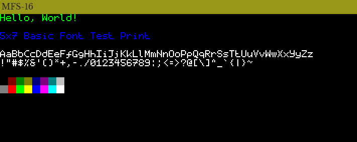
The MFS-16 has a display of 16 colours. Each pixel's 4 bits in VRAM denotes which palette colour that pixel is.
0x0 is the conventional background colour, and 0xF is the conventional foreground colour.
The 16 colours can be anything, but by convention they map to the 16 standard ANSI terminal colours:

The default MFS-16 palette.
| VRAM Pixel Value | ANSI Colour |
|---|---|
| 0x0 | Black |
| 0x1 | Red |
| 0x2 | Green |
| 0x3 | Yellow |
| 0x4 | Blue |
| 0x5 | Magenta |
| 0x6 | Cyan |
| 0x7 | White |
| 0x8 | Bright Black |
| 0x9 | Bright Red |
| 0xA | Bright Green |
| 0xB | Bright Yellow |
| 0xC | Bright Blue |
| 0xD | Bright Magenta |
| 0xE | Bright Cyan |
| 0xF | Bright White |
Since the VRAM bytes are processed sequentially by the screen, and words are written to memory in little-endian form, programs must account for the little-endian ordering when writing data to VRAM.
For example, to write the first 8 colours in the above table ordered left-to-right horizontally (i.e., black, red, green, ... cyan, white), the following instructions could be executed:
// Note the order of the nibbles!
// This will be written to VRAM as [0x01, 0x23, 0x45, 0x67].
LD BC, 0x67_45_23_01:d;
VLD [DE], BC;
MFS-16 Assembly
MFS-16 assembly language shares many similarities with other variants of assembly, but has some features that make it unique.
Comments
Comments can be single-line...
// Hello, I'm a comment. I am ignored by the MFS-16 assembler.
... or multi-line.
/*
    This is a big, multiline comment.

    It can be as long as you want.
*/
They can be located at any point in the line.
LD A,B; // This loads register B into register A.
Variables
Variables may be assigned at any point with the following format:
variable_name = number:data_type;
Since a semicolon ends the statement, variable assignments may be multiple lines.
Variable assignments do not take up any space in the final binary.
Valid variable names consist of alphanumeric characters, underscores, and numbers, but they cannot start with a number.
// OK!
my_variable = 255;

// NO! Must not start with a number.
12_my_variable = 254;

// NO! Illegal characters in variable name.
my+variable = 253;
After assignment, variables can be used in place of literal values (u4, imm8, imm16, imm32, etc.):
// This...
my_variable = 255;
ld A1,my_variable;

// ...does the same thing as this.
ld A1,255;
Literals
The data types of numbers must be explicitly specified by following the number with a colon, then a single letter denoting the data type. MFS-16 assembly supports four data types:
-
:b(byte): An 8-bit value. If no data type is given, the assembler will assume the value is a byte (and fail if the value is too large to be a byte!). Can be used with 8-bit virtual registers (A1, A0, B1, etc.). -
:w(word): A 16-bit value. Used with 16-bit registers (A, B, C, etc.). -
:d(double word): A 32-bit value. Used with 32-bit registers (BC, DE, HL). -
:q(quad word): A 64-bit value.
Decimal, binary, hexadecimal, and octal notation are all supported, and underscores may be used anywhere to visually separate the digits:
// OK!
ADD B0,123;

// OK!
CMP 0x1234:d, DE;

// OK!
my_double = 1_234_567_890:d;

// OK!
my_byte = 0xAB;

// OK!
MY_OTHER_BYTE_1234 = 0xCD:b;

// OK!
myoctalword = 0o780:w;

// OK!
a_quad
    = 0b_0101_0101_0101_0101_0101:q;

// NO! value is too large to be a byte.
my_byte_4 = 0x100:b;
Registers
The registers can be referenced by their (case-sensitive) names.
-
16-bit Registers:
A,B,C,D,E,H,L -
32-bit Big Registers:
BC,DE,HL -
8-bit Virtual Registers:
A1,A0,B1,B0,C1,C0,D1,D0,E1,E0,H1,H0,L1,L0
These names are reserved and cannot be used as variable names.
Instructions
Instructions are based around the following format:
mnemonic [operand], [operand];
They always consist of the instruction mnemonic, optionally followed by its operands (separated by commas), and always ending with a semicolon.
Mnemonics are case-insensitive.
They can be spread across multiple lines because unlike other assembly variants, semicolons signal the end of the instruction:
// OK!
ld A, B;

// OK!
ld
    A,
    B;

// OK!
ld  A,  B;
Here are some more examples of instructions:
halt;

ld [0x0012_3456:d],BC;

JP my_address;

InC DE;
Dereferences
Brackets [, ] are used to dereference addresses:
// Load my_word into memory at address BC
LD [BC],my_word;

// Load the value stored at address HL into A
LD A,[HL];
Named Labels
Named labels are globally-scoped identifiers that point to a specific location in the program ROM. Internally, the labels are 32-bit memory addresses which can be jumped to and referenced in other ways like a normal double word variable. The assembler places them as early as possible within memory.
Named labels follow the same rules for variable names and they take the following format:
label_name:
Their scope extends across all files used to assemble the final binary, and can be referenced before or after their declaration.
In the following example, the program counter travels from locations 1-4 in order:
// LOCATION 1 (START)
jp start;

// LOCATION 2
start:
jp label_2;

// LOCATION 4 (FINISH)
label_1:
stop;

// LOCATION 3
label_2:
jp label_1;
Explicit Labels
Exact addresses in memory can be denoted through explicit labels. They follow the same format and scope as named labels, but they are double word literals instead of variable names:
// The assembled binary code after this label starts at address 0x200 in memory.
0x0200:d:
// This instruction will be located at address 0x200 in memory.
ld A1,123;
They are commonly used for interrupt handlers, because CPU interrupts always jump to the same memory address:
0x100:d:
    // Handle frame interrupts
    call my_frame_function;
reti;

0x200:d:
    // Handle keyboard interrupts
    call do_something_when_keys_pressed;
reti;
Keep in mind that the assembler will fail if there is an explicit label that is too small:
// OK! Since this is the start of the ROM, the first two bytes are simply empty.
0x00_0002:d:
ld A,0x123:w;
ld B,0x456:w;
add A,B;
/*
    NO! The instructions above start at 0x00_0002 and take up more than two bytes
    of memory. 0x00_0004 is too small of a value.
*/
0x00_0004:
divu A,B;
This also means that the order in which you give your files to the assembler matters- since files are assembled sequentially, the explicit labels of files later on in the sequence must take the size of files earlier in the sequence into account when definint explicit labels.
Raw Byte Arrays
Raw bytes can be defined at any point in memory through raw byte arrays. Raw byte arrays have the following format:
[
  [bytes],
]
The bytes can be variables, the type suffix can be omitted, and commas are optional:
// OK!
[ 0x01:b, 0x23:b, 0x45:b ]

// OK!
[ 1, 0x23, 0x45 ]

// OK!
[
    0x01
    0x23
    0x45
]

// OK!
b1 = 0x01;
b2 = 0x23:b;
b3 = 0x45;
[ b1 b2 b3 ]
They are typically used in tandem with explicit labels in order to define some static data in ROM for future usage, such as raw bitmap data:
// Set DE to the start of sprite data
ld DE, sprite_data;
// Set HL to the start of VRAM
ld HL, 0x0100_0000:d;
// Write sprite data to VRAM
ldi BC,[DE];
vldi [HL],BC;
ldi BC,[DE];
vldi [HL],BC;

0x0000_1000:d:
sprite_data:
[
    0x12 0x34 0x56 0x78 0x9A 0xBC 0xDE 0xF0
]
Assembler
The assembler is given a list of files to assemble. The order of the files matters, as the files are simply appended to each other and processed accordingly.
In the following example, another_file.mfs16 is appended to the end of file.mfs16. Any variable assignments in file.mfs16 apply to another_file.mfs16, but they can be overwritten!
mfs16assembler path/to/file.mfs16 path/to/another_file.mfs16
If the assembler is not given an output file, it sends the resulting binary to stdout. An output file can be given using the -o option:
mfs16assembler my_program.mfs16 -o bin/my_program
The assembler won't overwrite existing files by default. This behaviour can be overridden by adding the -f flag.
Demo Programs
The MFS-16 repository contains some compiled demo programs in the programs/ directory. The assembly source files are included as well.
-
fibonacci: The first-ever MFS-16 program! Calculates the 12th Fibonacci number and stores it in the L register. No graphical output.
-
hello_world: Displays some text and the 16-colour palette.
-
pixel_test: Covers the screen with some colourful gaudy lines to make sure the screen is working. May cause eyestrain.
-
bouncing_ball: An ugly "ball" that bounces around the screen.
-
bouncing_logo: Bounces the MFS-16 logo around the screen.
![]()
-
toggle_screen: Displays the same awful pattern as
pixel_test, but the pattern can be switched on and off with a key press. -
kb: The bare-minimum keyboard test. Lights up pixels on the screen corresponding to pressed keyboard keys.
-
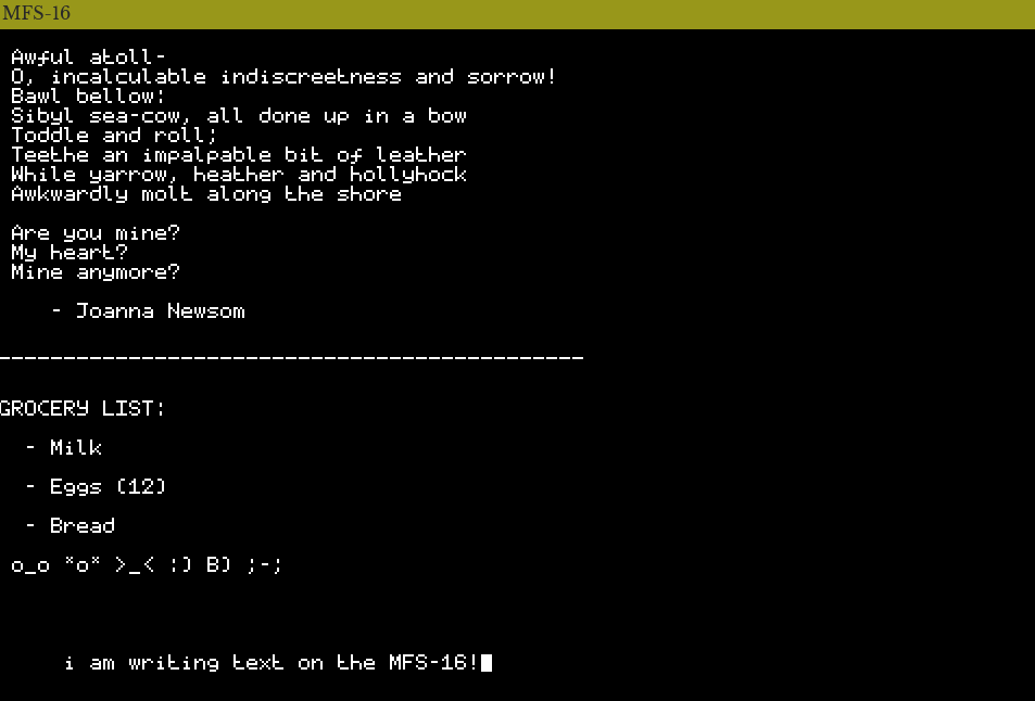
scribe: Type and erase text! File saving coming soon...
- promenade: Move a colourful square around the screen.